


Because military assets of the past, present, and future remain in use for decades after their initial production, corrosion will continue to be an important and costly issue for the Army and Department of Defense (DoD). According to an LMI study [1], the estimated annual corrosion cost in the Army alone is more than $3 billion, which is more than 12% of the Army’s total annual maintenance cost. Corrosion is also attributed to an estimated annual 719,441 nonavailable days for Army ground vehicle, missile, and aviation assets. Furthermore, within the entire Department of Defense (DoD), the estimated annual corrosion cost is $20.6 billion and more than 1.1 million nonavailable days. This estimation is nearly 20% of the DoD’s annual maintenance costs and more than 8% of the nonavailable days. Thus, effective corrosion prediction and prevention methods and tools can add immense value in helping to reduce life-cycle costs and prevent catastrophic failures to Army and other DoD systems.
CURRENT CORROSION TESTING AND VALIDATION
Currently, retrofits and new designs for Army vehicles are validated for corrosion performance by the Accelerated Corrosion Deterioration Road Test (ACDRT). Unfortunately, the ACDRT occurs relatively late in the design cycle, as it is performed on a fully operational vehicle after initial production has already begun. The ideal time to determine corrosion performance is during the initial design phases of the vehicle, as any design changes to improve corrosion performance can be made cheaply and quickly at this point in the process. On other hand, changes made at the time of the ACDRT are often costly and time consuming. The test itself is also expensive and relatively long, which can be made even worse if several tests need to be conducted due to design changes. The ACDRT has also been found not to mimic corrosion performance in the field for certain materials. However, the bottom line is that the ACDRT is the only corrosion test in existence for Army vehicles, and there is currently no full-scale vehicle modeling and simulation (M&S) tool for corrosion in use by the Army or other Services.
FUTURE CORROSION TESTING AND VALIDATION
Based on the current need for a relatively quick, easy, and cheap method for corrosion evaluation, the Accelerated Corrosion Expert Simulator (ACES) system was developed. The first full-scale vehicle corrosion M&S tool for use by the Army or other Services, ACES is designed to predict the initiation and growth of corrosion on any asset over time. The system is able to simulate the coating and corrosion performance in a multitude of scenarios and can display any deterioration that occurs at defined time intervals. It can also be used to quickly and cheaply perform trade-off studies of possible design changes— such as alternative geometries, materials, or coatings—to determine how they affect the asset’s corrosion performance.
The U.S. Army Tank Automotive Research, Development and Engineering Center (TARDEC) intends to use the ACES tool for new programs and any redesigns when possible. Other entities outside of the Army are also interested in using, or have already used, the tool. Currently, running an ACES simulation on Army programs is not mandatory, and full vehicle field corrosion testing (ACDRT) continues to be the basis for certification of new procurements. As the ACES tool continues to be improved, however, it is hoped that the use of such computer simulation will replace some, if not all, of the required physical testing.
At this stage in its development, ACES is simply used as an up-front, early-stage screening for corrosion issues. This limited usage is because there have been a number of corrosion issues where ACES was not able to successfully predict, or has mispredicted, the corrosion observed in the ACDRT or in the field. Once the simulator has matured to the point of achieving a 95% prediction success rate for the majority of the time, ACES will become the primary validation test for new designs and retrofits.
Once the simulator has matured to the point of achieving a 95% prediction success rate for the majority of the time, ACES will become the primary validation test for new designs and retrofits.
How ACES Works
ACES analysis begins with importing a full three-dimensional (3-D) computer-aided design (CAD) model of the vehicle, aircraft, ship, etc., together with the materials, coatings, and any ancillary information associated with every part. The user can then select preloaded scenarios in four different categories that relate to the vehicle, its operation, and its application. These categories are as follows:
- Environment – which includes temperature, humidity, salt, mud, ultraviolet (UV) exposure, vibration, chipping, etc.
- Maintenance Activities – which include washing, drying, lubrication, joint exercise, etc.
- Operating Profile – which includes ground time, storage, gravel roads, fording, loitering, takeoffs/landings, etc.
- Accidental Contamination – which includes animals, chemical spills, mercury, lavatory spillage, fire residue, etc.
Initially, ACES divides the vehicle into separate zones, each having its own specific environmental scenario, or microenvironment. This division is necessary because, for instance, a part in the engine compartment of a vehicle experiences a much different environment than a part on the roof. All of this information is used by ACES to determine the likelihood of corrosion occurring over time.
To date, ACES has gone through validations in the automotive and aviation fields, but the tool has the potential to be used in other applications as well (as illustrated in Figure 1 [2]).
![Figure 1: ACES Architecture [2].](/wp-content/uploads/2019/11/dsiac-journal-spring-2018-aces-sabiston-figure-1.jpg)
Figure 1: ACES Architecture [2].

Figure 2: ACES Structure/Process Map [2].
To perform the corrosion analysis, the ACES tool uses a combination of procedural physics-based (electrochemical) and artificial intelligence statistical-based techniques. Figure 2 shows a schematic of the procedures and processing that occur within ACES.
Beginning on the right side of the figure, the 3-D CAD models are imported into the tool as a STEP AP214 file [3]. All of the materials, coatings, and ancillary data must be either imported with the STEP file, as separate Excel spreadsheets, or input by the user. The integrity of the geometry is then validated, ensuring there are no duplicate parts, parts without a defined geometry, or invalid geometry description. The geometry of the model is then analyzed to define part interactions. This geometry includes parts that are in physical contact as well as those within a certain distance (or “area of influence”) of the selected part. Nearby parts can affect the corrosion performance of a selected part without being in direct contact; therefore, all of these interactions must be defined. All the information is stored in the working memory, along with the user-defined scenarios (operating, environmental, etc., profiles).
The left side of Figure 2 represents the knowledge base of the tool, which includes the preprogrammed rules, methods, models, and relationships that are based on corrosion principles and that are used to perform the analysis on the information in the working memory. The ACES tool’s reasoning module uses the input information and its knowledge base to output the likelihood of corrosion occurring.
Benefits
The ACES tool has many possible benefits in its current configuration. First and foremost, it offers a fast and inexpensive review of corrosion vulnerabilities in new designs, as well as updates to old product designs. In this way, ACES can shorten the development phase of a product’s life cycle by finding corrosion issues much earlier than waiting for the results from the ACDRT. Therefore, any changes to the product can be made earlier in the development, which is much easier, cheaper, and quicker to implement than waiting to make changes after the ACDRT is completed.
ACES can also assist with selecting geometric shapes and materials for optimal corrosion performance. A part’s material and geometry can be changed and a new corrosion simulation quickly performed to demonstrate how that change will affect the corrosion performance of that part or area. ACES should also be able to help predict when corrosion-based maintenance needs to be performed and give an estimate as to the life expectancy of a part due to corrosion.
Overall, the use of ACES should lead to a more corrosion-resistant product that uses maintenance personnel more efficiently, thereby reducing the cost of maintenance and repair (and subsequently the “cost of corrosion”), with an improved system reliability and fleet readiness. Furthermore, additional benefits are expected as ACES continues to be upgraded and improved in the future.
The ACES simulator has undergone two phases of acceptance testing:
- Calibration testing by GCAS Incorporated, the company that developed the simulator.
- Third-party validation testing by Oshkosh Defense, a manufacturer of many Army and Marine Corps vehicles
Calibration of the ACES Algorithms
The algorithms used in the ACES tool were first calibrated using ACDRT data from the Army’s Family of Medium Tactical Vehicles (FMTV). In general, ACES correctly predicted the corrosion performance of most parts over time. There were two highly notable and impressive predictions.

Figure 3: T-Handle Door Assembly Corrosion,
Material/Coating Information, and ACES Prediction [2].
The first was the successful prediction of severe corrosion of the T-handle door assembly, which initially suffered heavy corrosion on the T-handle itself and the carbon steel dish behind the handle (as shown in the top photo in Figure 3).
The middle drawing in Figure 3 is a cross section of the assembly with the material and coating information noted. The original design of the assembly was a die-cast zinc T-handle with electrophoretic paint (E-coat) and chemical agent resistant coating (CARC). The assembly also included a carbon steel pin, shaft, and washer; a zinc-plated carbon steel dish with an E-coat and CARC; and a carbon steel panel with no coating whatsoever. The interactions of the zinc-plated dish and die-cast zinc handle with the rest of the carbon steel parts, including some with no coating, caused galvanic and crevice corrosion of the handle and dish.
The ACES Version 0.9 correctly predicted these corrosion failures (as seen at the bottom of Figure 3 in the colorized likelihood of corrosion levels). Red-colored parts signify a severe level of corrosion, blue represents no corrosion, green represents an acceptable level of corrosion, and yellow (not pictured) represents a critical level of corrosion. The ACES predictions matched the experienced failures seen in the photo.
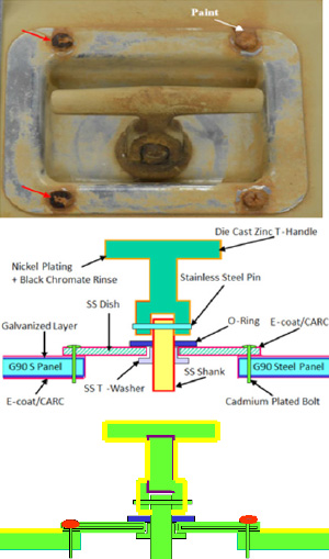
Figure 4: Redesigned T-Handle Assembly
With Minimal Corrosion, New Material/Coating Information,
and ACES Version 0.9 Correct Prediction [2].
Due to the corrosion failure of the initial design discussed previously, the T-handle assembly was redesigned (as shown in the middle drawing of Figure 4) to have a nickel-plated zinc handle and stainless steel dish, pin, shank, and washer. The steel door panel was galvanized, and an E-coat/ CARC was added. The result of the redesign was significantly better corrosion performance. Both the ACDRT of the redesign (as shown in the top photo in Figure 4) and the ACES Version 0.9 prediction (as shown in the bottom of Figure 4) indicated that the only severe corrosion occurred on the bolts holding the dish.
Over time, new enhancements have been incorporated into the ACES algorithms with the expectation of improving the accuracy of the predictions. However, in the case of the T-handle door assembly, unexpected behavior occurred. Although the current version of ACES, Version 1.3, continued to correctly predict the corrosion of the original design (Figure 3), it now incorrectly predicts corrosion performance of the redesigned assembly. Figure 5 shows the current version incorrectly predicts unacceptable severe corrosion of the nickel-plated handle and the galvanized door panel. It also does not predict any corrosion of the bolts holding the dish, which were the only parts that did experience corrosion during the ACDRT retesting.

Figure 5: ACES Version 1.3 Incorrect Severe Corrosion Prediction of T-Handle and Door Panel [2].
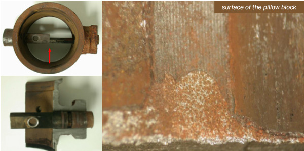
Figure 6: Engine Break Butterfly Shaft Seized Inside Iron Pillow Block [2].

Figure 7: ACES Prediction of Pillow Block Corrosion (Severe) and Butterfly Shaft Corrosion (Critical) [2].
A second example of a highly successful prediction was the FMTV engine break. This assembly suffered a safety-critical failure due to its butterfly shaft seizing inside the part (as shown in Figure 6). This failure occurred due to galvanic corrosion from the stainless-steel butterfly shaft passing through the iron pillow block.
ACES Version 1.3 correctly predicted this failure as seen by the severe corrosion of the pillow block in Figure 7. This successful prediction highlights one of ACES benefits. If this issue could have been detected during the initial design phase of the product using ACES, significant time and money would have been saved by not waiting to discover the issue during the ACDRT.

Figure 8: Transmission Cooling Shroud Crevice and Galvanic Corrosion at Bolted Joints and Water Entrapment Area [2].
One notable calibration case study where ACES was not successful in predicting the experienced corrosion during calibration was the FMTV aluminum transmission cooling shroud assembly (shown in Figure 8). The shroud suffered severe corrosion in two distinct areas:
- At the fastener interface, which failed due to galvanic corrosion from using steel fasteners on the aluminum shroud and from crevice corrosion under the fastener heads (left in Figure 8).
- In an area that created a water trap, allowing water to pool and act as an electrolyte in that area, thus causing the corrosion (right in Figure 8).
The ACES Version 1.3 prediction did correctly show the severe galvanic corrosion of the shroud and critical galvanic corrosion of the fasteners but did not predict the severe crevice corrosion that occurred under the fastener heads (as seen in the left photo in Figure 9). The crevice corrosion on the shroud was intensified by the electrolyte entrapment, which occurred due the geometry of the assembly.

Figure 9: ACES Prediction of Galvanic Corrosion of Cooling Shroud (Severe) and Fasteners (Critical) [2].
These calibrations on the FMTV showed that the current version of ACES can redict the corrosion of most parts on the vehicle, and significant success stories are noted, such as the engine break and the galvanic corrosion of the original T-handle door assembly. However, the latest version of ACES was not yet able to correctly predict galvanic corrosion of the nickel-plated T-handle, crevice corrosion of fasteners, and crevice corrosion due to water or electrolyte entrapment that occurred during the FMTV testing (which was used to calibrate its algorithms).
Validation Testing
After the calibrations of the algorithms were completed using the FMTV ACDRT, further independent “validation” testing was performed by Oshkosh Defense based on an ACDRT data of Oshkosh’s Marine Corps Medium Tactical Vehicle Replacement (MTVR). Elzly Technology Corporation was employed to conduct corrosion inspections of the MTVRs and developed a list of 27 hotspots where corrosion most prevalently occurred. Oshkosh selected four different assemblies on which to perform ACES validation testing that encompassed 12 of the Elzly-defined hotspots. These four assemblies were the (1) frame, (2) air tanks, (3) cargo body, and (4) fuel tank straps. ACES validation testing on the cargo body and air tanks are still underway, but the tank fuel straps and frame validations have been completed.
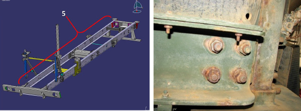
Figure 10. MTVR Frame Rail With Crevice Corrosion on Fasteners [2].
The frame rail hotspot consisted of all the fasteners on the frame, which suffered from severe crevice corrosion (as shown in Figure 10). ACES Version 1.2 correctly predicted this crevice corrosion failure, but Version 1.3 did not, and the prediction algorithms for crevice corrosion of fasteners is one of the enhancements currently being worked for improvement.
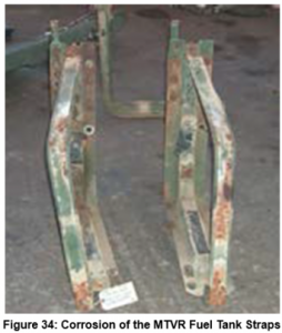
 Figure 11: MTVR Corroded Fuel Tank Straps [2].
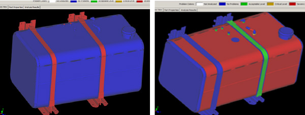
Figure 12: ACES Prediction of Severe Uniform Corrosion of MTVR Fuel Tank Straps (Left);
Incorrect ACES Prediction of Severe Galvanic Corrosion of the Fuel Tank (Right) [2].
The MTVR fuel tank straps suffered from uniform corrosion (as shown in Figure 11). This corrosion was correctly predicted by ACES (as seen in Figure 12, top). However, ACES incorrectly predicted the entire fuel tank to corrode due to galvanic corrosion (as indicated by Figure 12, bottom).
Based on the calibration and validation results, it was determined that several enhancements were needed to improve ACES and make it more accurate and reliable. These enhancements include adding a coating deterioration component, better handling of sacrificial coatings, adding crevice corrosion algorithms for fasteners (as well as other joint types), and predicting corrosion severity instead of just the likelihood of corrosion. Corrosion severity is how the Army rates corrosion in the ACDRT.
CONCLUSION
As discussed, the ACES simulator has the potential to be a highly useful tool in many fields—not only for military vehicles but also for aerospace, ships, bridges, rail, gas and oil pipelines, and facilities. And the Army believes that the tool will result in significant reduction in the future cost of corrosion and improvement in fleet readiness.
As the calibration and validation testing demonstrated, there are still areas of ACES that need to be improved, and improved prediction algorithms need to be added. Currently, the tool can acceptably predict galvanic, crevice, and uniform corrosion, but it has issues with certain areas, such as the crevice corrosion in fasteners. These issues will be addressed in the next release of ACES.
In addition, algorithms for the corrosion of joints, such as gaskets, spacers, moving joints, T-joints, sandwich joints, butt joints, and L-joints, need to be developed. Other needed enhancements include (1) the proper handling of sacrificial coatings, (2) the methods and logic for electrolyte accumulation/entrapment, (3) a video representation of corrosion progress over time, and (4) the changing of the output from the likelihood of corrosion to the Army corrosion severity levels.
A final future proposed enhancement is the addition of a knowledge acquisition facility within ACES, including learning algorithms for updating the tool’s knowledge base—effectively making the tool a robust “Watson-like” prediction system.
References:
- Hertzberg, E., T. Chan, R. Stroh, and N. O’Meara. “The Estimated Effect of Corrosion on the Cost and Availability of Army Ground Vehicles.” Report DAC21T2, LMI, February 2013.
- Savell, C. T., S. Woodson, S. Porter, J. Repp, P. Ault, A. Thiel, and B. Hathaway. “ACES: A Simulation and Modeling Tool for Vehicle Corrosion.” Paper, 2017 NDIA Ground Vehicle Systems Engineering and Technology Symposium, Novi, MI, 8–10 August 2017.
- Wikipedia. “ISO 10303.” https://en.wikipedia.org/ wiki/ISO_10303, accessed 11 January 2018.