


The selection and application of advanced composite materials play a critical role in the quest for improving performance of air and ground vehicles to meet ever-changing requirements. Unique properties of composites provide designers with the capability to customize structural characteristics of components and structures while yielding a reduction in weight over metallic counterparts. Initial application of composites to vehicles was applied to secondary structures, but as these composites and applications have matured, they have been expanded to primary structures. One of the most challenging applications has been to dynamic components, such as transmission drive shafts associated with rotary-wing aircraft. The development of composites with high levels of damage tolerance, coupled with unique manufacturing processes, has made their application to drive shafts a reality.
The use of an IM7/polyetheretherketone (PEEK) composite using in-situ tape placement fabrication technology has demonstrated the ability to construct a composite damage-resistant, ballistic-tolerant rotary-wing drive shaft. Through an evolutionary process, design data and techniques were developed to support this application. Test shafts were designed and fabricated, and their performance was validated. In addition, design/material data were evaluated to identify any data gaps that would obstruct transition of the technology to a production environment. Through a building-block approach, shafts were developed, design tools were validated, and test shafts were created for a ground test vehicle to support system design tests. In addition, an expansion program has been designed to transition the developmental shafts to a production configuration. This expansion program includes addressing identified design and data gaps, developing inspection processes, and developing manufacturing support processes and techniques required for the production of a flight-critical drive shaft.
Historical Perspective
The first significant application of composites material to a military helicopter was made by Boeing Helicopters in the 1980s with its experimental technology demonstrator medium-lift tandem-rotor cargo helicopter, the Boeing Model 360. While Boeing and other aircraft companies were pursuing potential applications of composites to existing and future platforms, the number and types of composites being made available were rapidly increasing.
In 1981, International Chemicals Industry (ICI) introduced a PEEK thermoplastic under the name of Victrex. This material was a semi-crystalline polymer with a maximum 48% degree of crystallinity. The counterpart composite material was introduced a year later as APC-1 with a 52% fiber volume, and it was optimized to yield APC-2 with a 63% fiber volume. The fiber adhesion properties of APC-2 resulted in superior impact and crack resistance compared to the APC-1, as well as existing epoxy-based composites. With a concerted effort by ICI Fiberite to develop manufacturing processes, in-situ tape placement was developed. The process, when coupled with the material properties, provided an ideal composite material for a drive shaft application.
To support various developmental activities, material data were created and used to develop preliminary design allowables and methodologies that were applicable to the design of drive shafts. From this work, shaft designs were ultimately developed to support the RAH-66 Comanche program, and the tail rotor drive shaft was planned to be constructed out of IM7/PEEK. When the Comanche program was cancelled in 2004, however, this work was suspended.
In 2010, work on an IM7/PEEK drive shaft was reborn via a U.S. Navy Naval Air Systems Command (NAVAIR) Small Business Innovation Research (SBIR) program, with the CH-53K as the target platform. Prior to initiating this program, it was necessary to reconstruct the design processes and design allowables from previous Army research programs and available data. The results of this program have demonstrated the feasibility of a highly survivable (i.e., ballistic-tolerant) thermoplastic composite drive shaft and have illustrated the ability to customize the design to meet unique shaft properties, such as frequency, thus raising the technology readiness level (TRL) to a point that would support transition to production.
NAVAIR SBIR
The 2010 NAVAIR SBIR (titled “Innovative Material Design and Manufacturing Development for a Lightweight, Low Cost, Highly Survivable Drive Shaft”) picked up on the initial industry research leveraging lessons learned and material characterization efforts of IM7/PEEK thermoplastic and furthered the technology to produce a highly survivable drive shaft. There were two phases for this program demonstrating the survivability capability of the IM7/PEEK drive shaft, as well as the ability to customize its properties to meet stringent design requirements. Supplementing this initial research is an expansion program designed to transition the work from Phases 1 and 2 to a production shaft with the required level of material characterization (i.e., design allowables and material properties), manufacturing process development, inspection techniques, and process validation through analysis and test.
While conducted in two phases, the shaft development work has consisted of the following three distinct elements:
- Design Allowable Evaluation and Verification
- Design Process/Analysis Development and Expansion
- Ballistic Design, Test, Evaluation, and Demonstration.
Design Allowable Evaluation
B-basis design allowables (90% probability with 95% confidence) recreated from data used in previous Army experimental programs were evaluated to determine viability in supporting a drive shaft design and to identify any data gaps that would require resolution to support technology transition to a production application. While a large database of material information is required for establishing B-basis design allowables, the database for the IM7/PEEK allowables was limited. In addition, ongoing processing improvements designed to reduce void content meant that the material property values would be changing with the process evolution. To account for the limited property database, advanced statistical regression techniques were used in accordance with MIL-HBDK-17 (CMH-17) guidelines for pooling data where insufficient data from a single fiber/resin configuration are available (as long as all the pooled data possess the same resin matrix).
Due to limited data availability, it was necessary to pool data from AS4, IM6, and IM7 PEEK to develop a material database of adequate size to develop B-basis allowables. In addition, the available data used in this process were taken from different fabrication processes and were not exclusively representative of the in-situ tape placement process used for drive shaft fabrication. The data were grouped as determined appropriate by batch analysis studies. The justification for this approach relies on the resin-dominated properties being the same coupled with an understanding of the fiber contributions to the overall material properties.
Because autoclaving and press curing were used to manufacture the test specimens to develop the design allowables, it was necessary to cross-walk these values against the material properties produced using the in-situ tape placement process used to fabricate the drive shafts. From this evaluation, it was determined that the existing design B-basis design allowables were acceptable for development of prototype shafts as they tended to underpredict performance. However, to support transition to production, the allowables would have to be refined to better account for the in-situ tape process-generated properties. This conclusion came from comparison of properties developed through a series of material property tests configured to provide a material property comparison between the in-situ process and data used to create the B-basis allowables. The in-situ developed data were compared with the preliminary B-basis allowables and the respective database. From this comparison, it was determined that while shear-dominated properties require additional refinement, the current B-basis allowables are adequate to support initial design of a drive shaft and represent a conservative approach.
Design Process Development
To facilitate the laminate design of the shaft, a process was required to quickly evaluate different ply orientations and layups for their ability to meet the program objectives. This evaluation process was achieved by using classical laminate theory with the Tsai-Wu failure criteria. Relationships were developed in an engineering calculation software package. They were developed in a manner permitting simple modification of the laminate orientation and applied torsion load to determine torsional load capability. The analysis evaluates the shaft configurations for torsional buckling and strength in the undamaged configuration, as well as torsional strength in the damaged configuration. The damaged configuration is developed by introducing elliptical damage into the calculation meant to simulate the amount of damage expected from a ballistic event. This degree of damage was developed from previous test data and represents an estimate of expected damage from the ballistic threat defined for this program.
Analysis assumptions used Kirchhoff hypotheses, which assume all normals remain straight (do not bend), unstretched (keep the same length), and normal (always make a right angle to the neutral plane). In addition, perfect bonding is assumed for the laminate. This means the bonding itself is infinitesimally small (there is no flaw or gap between layers), it is non-shear-deformable (no lamina can slip relative to another), and the strength of bonding is as strong as it needs to be (the laminate acts as a single lamina with special integrated properties). From this analytical approach, it was possible to quickly assess different fiber orientations for weight, torsion capability (with and without ballistic damage), lateral stiffness, and frequency.
Drive Shaft Design Parameters and Fabrication
As mentioned, drive shaft design parameters were derived from the CH-53K helicopter platform. The goal of the composite design was to determine the architecture required for a thermoplastic composite driveshaft to be a direct replacement for the existing aluminum shaft. A minimum 15% weight reduction over that of the aluminum shaft, which equates to approximately 0.213 lb/unit inch of shaft length, with no reduction in performance was required. The composite shaft was required to possess the same geometry as the existing shaft with an inner diameter (ID) of 6.25 inches and an outer diameter (OD) of 6.5 inches. The drive shaft configuration would have to experience temperatures of -40 °C (-40 °F) to +50 °C (+122 °F) during continuous operation and of -54 °C (-65 °F) to +71 °C (+180 °F) in a nonoperating or storage and transport capacity. The natural frequency cannot exceed 15% of 118% of 4,269 rpm. Torsional loads must be fully reversible, and unbalanced forces must be constrained to 2.8 gm-in at operating speed.
Several design configurations were developed for this program to evaluate the effect of fiber orientation on the mechanical properties and optimize the design (greatest properties for least weight). A typical IM7/PEEK composite drive shaft is shown in Figure 1, which was processed with the in-situ tape placement process shown in Figure 2.


In the in-situ tape automated fiber placement (AFP) process, the thermoplastic composite tape (i.e., IM7/PEEK) is applied to a mandrel via an automated process that first heats the raw material using a hot gas torch stream and then consolidates/compacts the laminate with a rigid steel roller. The heating agent is nitrogen gas, which is heated as it passes through an electrically resistive heating element to elevate the raw material temperature up to its melting point. The material is then passed between a rigid steel roller and the processing tool to consolidate the material. The first layer of material is placed onto a cold tool. Subsequent layers are placed on top of the previous layers to form the laminate of desired thickness and fiber orientation. Each new layer is melt-bonded to the previous layer. The laminate is built to the desired specifications and then removed from the tooling. At this point, the laminate is considered complete. There is no post-processing needed. The part is then trimmed to the desired geometry and is ready for use.
Drive Shaft Design Verification
The ballistic and static torsion properties were validated through a series of ballistic and static tests that used a test fixture (shown in Figures 3 and 4) supplied by the NAVAIR China Lake Test Facility. Torque was applied through a rotation disc via actuators, and a digital inclinometer was used to support measurement of shaft rotational angular deflection.


The test fixture was modified to accept a composite driveshaft, and the appropriate actuator arrangement (actuators, pump, and controls) to support the loads (introduction rates and magnitude) required for both the ballistic and post-damage torsion-to-failure tests was included. In addition, a data acquisition system (DAQ) was designed and fabricated to record readings from the load cells (used to measure applied torque) and a digital inclinometer (used to measure shaft angle). To exercise the capabilities of the fixture prior to beginning the test sequence, a test shaft was used to evaluate the fixture functionality.
The range configuration illustrated in Figure 5 shows the orientation of the test fixture in the range with the hydraulics nearest the gun barrel to minimize damage potential, and Figure 6 shows the actual test setup.


The ballistic test fixture design incorporated an actuator system to apply and maintain a predefined torsion load during test and to increase loading at a 20,000 in-lbf/min rate until failure of the test shaft occurred. Throughout the load application, the angular deflection of the shaft was measured. A plot was generated comparing reacted torque as a function of angular deflection to characterize the performance of the shaft. Of the tests conducted, all but two tests were conducted at room temperature dry (RTD) conditions. The two exceptions required thermal conditioning prior to the ballistic event. One shaft was conditioned at +180 °F and the other at -40 °F. Thermocouples were used to verify that the appropriate conditions were achieved and present during the ballistic event.
Design verification testing of the ballistic damaged shafts included the following:
- The ballistic impact load was set at 32,000 in-lbf of torque to simulate the worst-case flight scenario during an impact event, with the load application set in the direction that would cause the damage from the event to close on itself. Testing on a slotted shaft realized lower torsion levels with the load applied so as to close the slot as compared to one in which the slot would open.
- The extent of ballistic damage was characterized by a nondestructive inspection (NDI) coin tap methodology.
- Thermal measurements for conditioned specimens were taken at several intervals prior to test, including at removal from the conditioning chamber, at installation into test fixture (start and end), and prior to the ballistic event.
- The weight of the shafts was measured to the hundredth of a pound before and after the ballistic event to determine approximate weight reduction due to material loss from the ballistic impact, which was used to determine potential shaft out-of-balance.
- The post-damage shaft was tested with a 20,000 in-lbf/min loading rate until failure of the test shaft.
- Drive shaft lateral stiffness was measured by the angular inclination of the fixture load application moment arm before, during, and after the ballistic impact event.
- Post-impact stiffness was measured using the angle of inclination as captured by the inclinometer and was recorded continuously during the post-damage test as a function of applied load.
- Both normal and tumbled projectile events were used to damage the test shafts. Figure 7 shows typical damage for each event type although the degree of damage varied for the test events.
 and Tumbled (middle and right) Impact Events.")
In each of the developed designs, the measured properties of the test drive shafts were greater than that calculated in the design process. As shown in Table 1, the calculated properties for the drive shafts underestimated the actual test results by approximately 50%.
Table 1. Design/Analysis Correlation.
|
Test Specimen |
No. of Plies |
Specimen |
Calculated Torque |
Calculated Torque |
Measured Torque |
Measured Torque |
Delta |
|
TP3 |
44 |
A |
258,500 |
49,200 |
NA |
63,814 |
30% |
|
TP7 |
44 |
A |
258,500 |
49,200 |
NA |
110,664 |
125% |
|
TP8 |
44 |
A |
258,500 |
49,200 |
NA |
53,603 |
9% |
|
TP12 |
44 |
A |
258,500 |
49,200 |
NA |
86,630 |
76% |
|
TP11A |
44 |
A |
258,500 |
49,200 |
NA |
92,555 |
88% |
|
TP4 |
44 |
B |
287,800 |
53,200 |
NA |
67,639 |
27% |
|
TP5 |
36 |
C |
197,600 |
41,700 |
NA |
64,616 |
55% |
|
TP6 |
36 |
D |
229,100 |
44,300 |
NA |
58,543 |
32% |
|
TP1 |
44 |
A (Spare) |
258,500 |
49,200 |
338,000 |
NA |
31% |
|
TP10 |
44 |
A (Spare) |
258,500 |
49,200 |
NA |
NA |
NA |
When considering specimens with similar degrees of damage (TP3, 4, 5, 6, and 8) the calculated properties consistently underpredicted by approximately 31%. Those with a lesser degree of visible damage were capable of supporting an even greater torsion load, resulting in a larger deviation between the calculated properties and test data.
Several factors attributed to the differences between the model and test results. These include:
- Conservatism built into the B-basis design allowables.
- The application of the Tsai-Wu first-ply failure approach to define the torsion failure point for the shaft. In reality, composite laminates often can support greater loads than that which may initiate failures in the laminates on an individual ply basis.
- The estimate of the damage in the analytical model. As the actual damage deviates from this condition, so does the torsional load from the calculated value.
- The degree at which the B-basis design allowables represent the mechanical properties produced using the in-situ tape placement process.
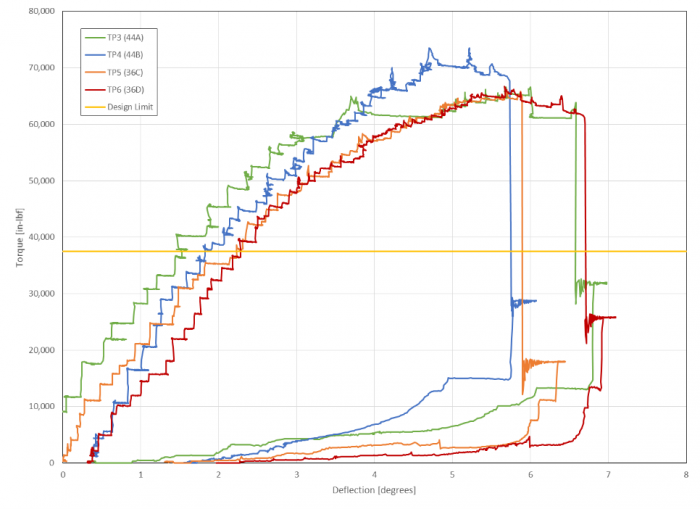
The effect of elevated and depressed shaft temperature did not adversely affect the torsion performance of the shafts. As with the room temperature tested shafts, both cases tested above the design limit torque. There was no apparent degradation in mechanical performance for either conditioned shaft. In considering the various design architectures, all of the shaft configurations performed above their respective design limits, and the failure modes were extremely similar (as illustrated in Figure 8).
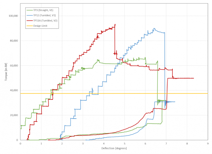
As illustrated in Figure 9, drive shafts impacted with tumbled projectiles (TP11A and TP12) exhibited a higher static ultimate torque than a similar shaft shot straight on. The visible damage for both tumbled round shafts was more localized to the impact zone than the straight shot shafts although the nonvisible delaminated region (as defined by the tap test) was larger. Note that TP11A experienced an initial decrease in load-carrying capacity at approximately 4.5° of deflection. Even after this decrease, the shaft still easily carried between 60,000 and 70,000 in-lbs although at this point the shaft entered progressive failure where every increase in applied load resulted in increasing deflection and lessening reacted torque.
In torsion testing of an undamaged shaft (no damage present), the failure occurred at the bolt pattern at a static ultimate torque level of more than 338,000 in-lbf. There was no apparent damage to the body of the shaft, and this measured failure level was 31% greater than that predicted by the analytical process.
During evolution of the designs, it became necessary to modify shaft properties for frequency response to improve overall drive train properties. This modification required reduction of the margin of safety associated with the shaft design in favor of developing the proper frequency response. Using the same analytical process for the ballistic shafts, a balanced design was developed and the frequency response of the resultant fabricated shaft was correlated against the analytical predictions using both stiffness and rap testing.
Conclusions
The NAVAIR SBIR program validated the potential of an IM7/PEEK drive shaft for application to a helicopter drive train. The program met all performance and gate requirements as defined in the statement of work and supporting documentation. A number of candidate shaft designs were fabricated based on coupon-level test data. These shafts successfully withstood a ballistic event under load and continued to meet performance requirements when they were torqued to failure afterwards. The effect of varying the layup, manufacturing process, projectile configuration, and temperature were examined in these tests. The candidate shaft designs all far exceeded the minimum weight reduction (15%) exhibiting weight reductions of up to 33%. In addition, it was demonstrated that the frequency response of the composite drive shaft, unlike its metal counterpart, could be tailored.
With these results, prototype shafts were delivered to support operation of a ground test vehicle and an expansion program was designed to produce the necessary data to transition the technology to a production variant for the CH-53K. Furthermore, the success of this program and previous research work has laid the groundwork for IM7/PEEK and its derivatives to be considered in numerous air and ground vehicle applications, both static and dynamic, offering advances in performance at lower weights than offered by traditional materials.
Acknowledgments:
The author wishes to acknowledge the following organizations and individuals for their invaluable involvement in this program: NAVAIR for its sponsorship of SBIR N101-097 (especially Ms. Leslie Leigh for her leadership and guidance in the execution of the program); Automated Dynamics for its program management and fabrication efforts to turn engineered designs into viable composite drive shafts; and Sikorsky Aircraft and United Technology Aircraft Systems (UTAS) for their general support and guidance. In particular, UTAS is acknowledged for its performance of frequency measurements and preparation of the shafts for use on the ground test vehicle.