


INTRODUCTION
When considering catastrophic failures in structures, one often imagines the worst-case scenario, in which a large force can cause an immediate destruction. However, events of these types are rare in nature. More often, a structure succumbs to fatigue failure long before any major destructive event can befall it. This fatigue can be an insidious threat to structures, as it is often imperceptible until the damage has occurred, resulting in a need to repair the structure and costing time and money. Thus, in the case of the aircraft industry, as more airframes see an extended life cycle, monitoring the strain and fatigue experienced by the aircraft has become increasingly important.
CURRENT METHODS OF MEASURING STRAIN
Strain Gages
Relatively inexpensive and reliable, strain gages have been used for decades to provide effective point-based measurement of strain in a material. As shown in Figure 1, the strain gage is made of a long, thin wire embedded in a thin material that is affixed, usually by adhesives, to the surface of whatever structure is being observed. When force is applied in a strain gage, it causes a geometric change in the gage, resulting in a change in the resistance of the gage as well. Applying Ohm’s law allows one to solve for the current, which can be translated into strain.
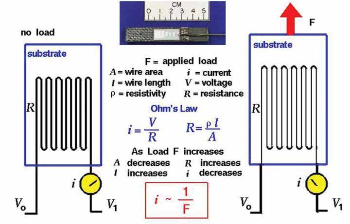
Figure 1: The Functioning of a Simple Strain Gage (Source: NASA) [1]
One downside to strain gages is that they must be individually wired and emplaced on a structure and connected to a data acquisition system. Accordingly, these limitations make large-scale wide-area monitoring by strain gages impractical.
Fiber Bragg Grating
A newer development for widearea monitoring is the Fiber Bragg Grating (FBG) sensor. As Yolken and Matzkanin describe in a paper for the Nondestructive Testing Information Analysis Center (NTIAC) [2]: Since the advent of photo-induced Bragg gratings in optical fibers in 1978, Bragg fiber gratings have found many applications in telecommunications and sensing. Bragg gratings have emerged as elegant in-fiber sensors particularly suitable for multiplexed and distributed applications. The growing interest and rapid progress made in the area of strain sensing using Bragg grating based sensor systems indicate recognition of the fact within the sensor community that fiber Bragg grating based sensors provide powerful sensing techniques which can be uniquely applied to a range of structural sensing applications.
FBG systems are made of fiber optic filaments that have had a series of highly reflective, frequency selective filters embedded throughout the length of the fiber. When temperature or strain is applied to a fiber section containing the grating, the grating spacing and index of refraction are modified, thus changing the Bragg wavelength [2]. Because FBGs work in the frequency domain, as opposed to the amplitude domain, the system can have large sensitivity due to small changes in the light wavelength.
Figure 2 provides a description of how FBGs measure strain due to shifts in the wavelength. The benefit of using FBGs is that any given length of fiber can have thousands of individual sensors embedded in it, which allows engineers to move beyond point-based measurement of strain as seen by strain gages and toward field-based sensing over large areas. This capability has direct implications in areas such as civil engineering, where large-scale structures are the norm. Engineers can emplace multiple fibers and create a web of sensors to track and monitor any changes seen in the strain profile. Also, due to the lightweight nature of FBGs, they can be readily applied to aircraft to provide wide-area interrogation of strain loads.
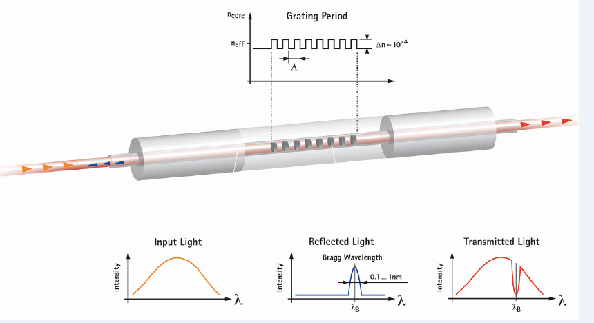
Figure 2: FBG Systems Monitor Reflected Light Off the Grating to Determine the Change in Fiber Length. As the Fiber Stretches or Contracts, the Reflected Light’s Phase Angle Shifts and Can Be Correlated Into Strain Change [3].
Figure 3 demonstrates how strain can be measured in aircraft structures. A foil strain gage provides point strain data, while two FBGs run down the length of the composite structure, providing wide-area interrogation profiles. Also shown is a “Smart Layer” consisting of FBGs woven within the composite panel itself. This process can provide even more detail into the internal strains experienced in flight, and it demonstrates how easily FBGs can be incorporated into aircraft structures.
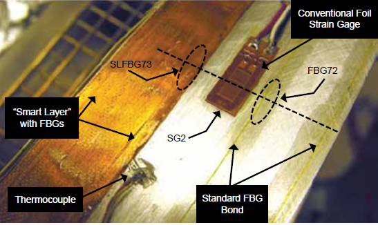
Figure 3: Three Methods for Measuring Strain in Aircraft Wings: Bonded FBG, Single-Point Foil Strain Gages, and FBG Incorporated SMART Layers With the FBG Embedded in the Composite Panel Itself [4].
NEW METHODS OF MEASURING STRAIN
Elastomeric Sensors
While strain gages and FBGs work well for traditional materials, as more less-rigid materials are introduced into engineering concepts, there is a need for strain sensors that can read higher strain loads beyond where traditional methods experience failure. One recent development is the creation of carbonfilled elastomers.
Figure 4 shows the work of Mattmann et al. on creating a strain sensor that can handle the loads seen in textiles [5]. Textiles typically can stretch well beyond the limits of metal or other rigid materials, rendering the use of traditional strain-sensing methods useless. To measure the high strain loads, Mattmann et al. filled a conductive thermoplastic elastomer with conductive carbon black and extruded the material into a filament. The underlying principle for the filament is that, as it stretches, its electrical conductivity changes, which directly correlates to the strain seen in the system.
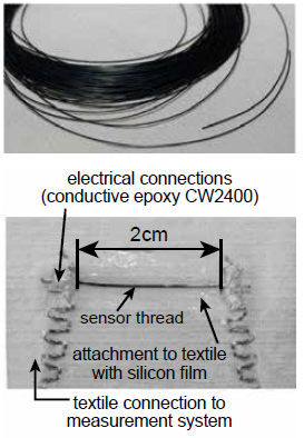
Figure 4: The Extruded Carbon-Filled Elastomer
Sensor Thread (top); The Sensor Thread Attached
to a Textile Layer With a Silicone Film (bottom) [5].
As Figure 5 demonstrates, in bench top testing, there is a strong correlation between the change in resistance and the experience strain. While this technology is still in its infancy and requires more testing before commercially viable sensors become available, the research shows strong promise for creating a sensor system that can measure high strain loads.
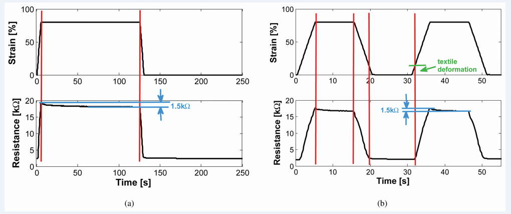
Figure 5: Strain Response for a 2-cm Sensor Thread
for 2-min Strain Load (left) and 10-s Strain Load (right) [5].
Frequency Selective Surface Sensors
Another emerging technology is the use of Frequency Selective Surface (FSS) sensors to remotely monitor strain in structures. Figure 6 shows how FSS sensors are used, with an array of elements applied to a structure surface. Once in place, the elements are illuminated using electromagnetic energy, and the reflected response is correlated to the strain profile of the underlying substrate. As the substrate shifts and moves due to strain, the elements in the array contort in response, which changes the reflected response seen by a remote interrogator.
Figure 6 shows the strain profile seen in the steel core of a column undergoing buckling. Note how the foil strain gages cover only a range of the entire loading sequence while FSS sensors show a much broader range of data capture. This broader range allows engineers to have a much more complete view of the loads experienced by the structure. FSS sensors are relatively inexpensive to produce, and multiple arrays can be distributed across a surface to create an array of arrays to provide complete coverage of an entire structure. And given that the entire system is wireless, large numbers of arrays can be installed without worrying about wires getting in the way or tangled.


Figure 6: An Array of FSS Elements on a Steel Core (top);
Strain Response of the FSS on the
Steel Core Compared to Strain Gages (bottom) [6].
Life-Cycle Analysis
No matter which method of strain measurement one uses, the strain data can be used for predictive life analysis. For example, NASA studied the effect of fatigue loading using FBGs on a B-52 front pylon hook (as shown in Figure 7). FBGs were used because of their high spacial resolution and ability to conform to complex geometries. Strain data collected from the FBGs can be fed into models such as the Walk crack growth equation, which will determine the amount of crack growth in each flight. Based on the calculated crack growth, engineers can calculate the remaining operational life for each component of the aircraft. And with constant monitoring of the parts through the use of embedded strain monitoring systems, the crack growth and operational life equations can be constantly refined through the operational life of the part.
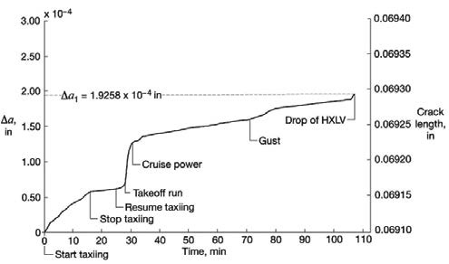
Figure 7: Crack Growth Curve of the B-52 Front Pylon Hook [4].
CONCLUSION
Strain measurement is an integral part of life-cycle analysis. Often times, minute changes in the strain profile of a component can have a large impact in the health of a part. Being able to detect, measure, and document the changes in the strain profile can help engineers and designers ensure that all components meet applicable safety standards. Additionally, as new sensor technologies continue to be developed and improved, engineers can keep adding to their set of tools for monitoring strain.
References:
- NASA. “Strain Gage.” https://www.grc.nasa.gov/ www/k-12/airplane/tunstraingage.html, accessed July 2017.
- Yolken, H. T., and George A Matzkanin. “A Technology Assessment of Bragg Grating Fiber Optic Based Nondestructive Evaluation (NDE).” NTIAC-TA-01-02, Nondestructive Testing Information Analysis Center, September 2001.
- Maul, Jochen, and Tobias Kipp. “Sensing of Surface Strain with Flexible Fiber Bragg Strain Gages.” HBM, May 2011.
- Richards, W. Lance, Allen R. Parker, William, L. Ko, Anthony Piazza, and Patrick Chan. “Application of Fiber Optic Instrumentation.” RTO-AG-160-V22, Research and Technology Organization of the North Atlantic Treaty Organization, July 2012.
- Mattmann, Corinne, Frank Clemens, and Gerhard Troster. “Sensor for Measuring Strain in Textile.” Sensors, vol. 8, no. 6, pp. 3719–3732, June 2008.
- Kinzel, Edward C., Kristen M. Donnell, and K. Chandrashekhara. “Structural Health Monitoring and Remote Sensing of Transportation Infrastructure Using Embedded Frequency Selective Surfaces.” NUTC R365, Missouri University of Science and Technology, July 2014.