


Introduction
Parallel processing divides large problems into smaller problems that can be run simultaneously on multiple processors. Although the technique has been around for decades, it has largely been under the province of high-end scientific computing on supercomputers. But that situation has changed dramatically in recent years as commodity computer manufacturers have switched to multi-core central processing units (CPUs) that now offer four, six, eight, or more computing cores (as illustrated in Figure 1). Today, virtually every desktop, laptop, and notebook computer is built for parallel processing. That’s the good news. The bad news is that most software is not designed for parallel processing, so the full power of these multi-core CPUs goes unused for many applications. Fortunately for weapons analysts, their principal simulation tool, endgame codes, are highly amenable to parallel processing and can take full advantage of multi-core CPUs to increase modeling and simulation (M&S) speed. Additionally, new capabilities that were not practically feasible before, such as near-real-time design optimization, can now be developed.

Figure 1: Typical Multi-Core CPU.
Admittedly, multi-core CPUs are not the only option for parallel processing. Multiple computers networked into a computing “cluster” are another option [1]. General-purpose computing on graphics processing units (GPGPU) is also receiving a great deal of attention [2]. However, the discussion for this article is limited to multi-core CPUs as one of the more affordable and easily implemented options that engineers and scientists have access to in their personal desktop and laptop computers.
TurbopPK: A Parallelized Endgame Code Project
In 2005, the authors of this article initiated an internal research and development (R&D) project to investigate parallel processing as applied to endgame codes, with a focus on ensuring traceability to Department of Defense (DoD) and industry standard methodologies and algorithms. That test bed has since evolved into a code called TurboPK. It is a traditional “point-burst” endgame code that runs on both Microsoft Windows and Linux platforms and can be used to simulate and analyze weapon kinetic energy and blast effects, including armor-piercing projectiles, fragments, exploding munitions, and air blast.
Unlike many legacy codes that generally only support a portion of the design optimization/vulnerability/lethality analysis, TurboPK is an all-inclusive munitions survivability and lethality engineering analysis and design code that supports design-to-PK (probability of kill) requirements. It creates shotlines, traces shotlines through geometric models, applies penetration equations, computes damage probabilities to vulnerable objects encountered along shotlines, and applies fault tree analysis to vulnerable component damage probabilities. In doing so, it adheres to accepted standards for core endgame algorithms (i.e., penetration equations, component damage functions, fault tree analysis, and personnel casualty/incapacitation criteria). And like other endgame codes, TurboPK can analyze single shotlines, grids of parallel shotlines, single burst points, and sets of burst points. Because burst point set analysis is the most common use of the code, it is the primary focus of this article.
Through investigation and implementation of various parallelization schemes and employment of various software development tools, we were able to demonstrate that parallelizing endgame codes is practical in terms of providing impressive reductions in simulation run times and that these improvements scale linearly over a small number of cores.
One obvious way to speed up the analysis of a set of burst points is to subdivide it into subsets that then run in parallel on multiple cores. The scheme employed in TurboPK is illustrated in Figure 2.
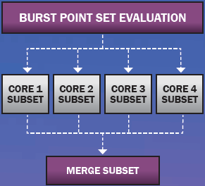
Figure 2: Typical Multi-Core Parallelization Scheme.
To implement this scheme, TurboPK creates a separate computational thread for each core, asks the operating system to launch the threads, waits for all the threads to complete their work, and then merges the results from all the threads. Each thread is a complete point-burst program. Point-burst simulations model a fragment warhead burst in Monte Carlo fashion as a set of fragment rays whose directions and speeds are randomized according to a prescribed distribution function. An example point-burst is depicted in Figure 3 as a set of fragment shotlines emanating from a point located a few meters above the target model of interest. In a point-burst code, each shotline is first ray traced against the target geometry model inquestion to determine which geometry objects, if any, it intersects.

Figure 3: Example of a Warhead Point-Burst Simulation.
The ray tracing step is computationally intensive and often consumes 80% of the runtime in a point-burst code due to the large number of potential ray-object intersection tests involved. Consider, for example, a warhead that ejects 2,000 fragments and a geometric model that has 100,000 triangles. In theory, that results in 200,000,000 ray-triangle intersection tests to be performed per point-burst calculation. Many such calculations are performed in a typical analysis session, so it is easy to see why ray tracing dominates the run time. Fortunately for endgame programmers, ray tracing has been the subject of a great deal of research, and there are numerous high-quality, open-source ray tracers that greatly reduce ray tracing times for endgame codes.
A number of ray tracers have been implemented in TurboPK over the years. The current default ray tracer is an open-source ray tracer called Embree [3], provided by Intel Corporation. Embree fits the scheme illustrated in Figure 2 because it is “thread safe.” That is to say, the code manipulates only shared data structures in a manner that guarantees safe execution by multiple threads at the same time. Embree also employs a low-level type of parallelism in the form of Single Instruction Multiple Data (SIMD) instructions [2]. Among other things, SIMD enables Embree to test one ray against four triangles simultaneously. The result is the addition of a layer of low-level parallel processing to the high-level multi-core layer.
So how well does all of this parallel processing work? Let us consider an example burst point set calculation where the burst point set is a rectangle of burst points located at a fixed height-of-burst (HOB) relative to the target model (a typical simulation that might be run by legacy endgame codes). The exercise will be performed on a typical desktop computer with an Intel i7 four-core CPU. The target model is an aircraft model that has a set of vulnerable components (pilot, hydraulic lines, wire bundles, engine controls, etc.) typical of industry and DoD standard target geometric models (TGMs). The warhead ejects 2,000 fragments in a 20-degree side spray. Fragment mass is 240 grains each, and fragment ejection speed is 6,000 fps. The missile carrying the warhead is approaching in anti-parallel fashion (head-on approach direction). Warhead burst points are spaced 0.328 m apart in a rectangle measuring 30 m by 30 m. The HOB is 8 m above the bottom of the target geometry. At each burst location, 100 Monte Carlo point-burst calculations are performed, each of which results in a PK value for the target of between 0 and 1 as a statistical indication of the likelihood of destroying or disabling the target in such a manner that it cannot perform its intended mission. Averaging the 100 individual point-burst PK values yields a single-shot-average-PK value for the burst point. Figure 4 illustrates the field of burst point markers color-coded by PK (blue equaling a probability of 0 and red equaling 1).

Figure 4: Example Burst Point Set Simulation and Display.

Figure 5. Simulation Results for Different Numbers of CPU Cores.
There were 8,281 burst locations in this calculation, so there was a total of 82,810 point-burst calculations. Each point-burst calculation involved 2,000 randomized fragment shotlines, so the total number of shotlines analyzed was 165,000,000. Averaged over all 8,281 burst points, the PK is 0.25 for this example. To illustrate the value of parallelizing the calculations, the simulation was run on a single core and then on two, three, and four cores (as indicated in Figure 5).
Run time for one core was 145 s and for four cores was 41 s, or a speedup factor of 3.54. That result is 88.4% of the theoretical maximum speedup factor of 4.0. Similar results have been demonstrated for other burst point set problems with different warheads types and configurations and different targets, including various ground vehicles, aircraft, and personnel. So it is safe to say that parallelizing endgame codes through multi-core computing is well worth the extra programming effort required.
Interactive Warhead Design: A Nontraditional Endgame Application
As demonstrated in the previous section, fully parallelized endgame codes can do what legacy codes do now, but much faster. That fact alone is a significant benefit worth implementing. Such speed increases also allow endgame simulations to morph into new, nontraditional forms that can provide the end user with tools that were previously neither time- nor cost-effective to implement on a desktop computer. This section presents an example of incorporating warhead design directly into endgame simulation to support “design-to-PK” requirements.
These days, warhead design is performed via highly sophisticated computational mechanics codes, such as the Combined Hydro and Radiation Transport Diffusion (CTH) [4] and LS-DYNA [5]. These codes are generally in the domain of experts and can provide highly accurate simulations of explosive-metal systems, but they are not typically considered to be fast-running. For some cases of interest, such as cylindrical-shaped fragmentation warheads, analytical approximations provide accurate first-order estimates of fragment ejection angles and speeds and also have the advantage of being fast-running (i.e., a few seconds) [6–8]. Because the authors have an interest in warhead design and endgame simulation, it was not difficult to extend the capability of the tool by adding warhead design directly into the TurboPK endgame simulation using the techniques described in Szmelter et al. [6], Charron [7], and Hennequin [8]. The idea is to enable a user-driven optimization loop. An optimization algorithm can also be added relatively easily (as illustrated in Figure 6), but currently the user steers all computations.

Figure 6: Addition of Optimization Algorithm.
An interactive warhead design session starts by loading the target model elements (geometry model, damage functions, fault tree, etc.) and defining a set of burst points. The warhead design feature is accessed through the dialog box pictured in Figure 7. The warhead design described by the parameters in Figure 7 is a cylinder 10 inches long and 8 inches in diameter. The fragment case consists of cubes whose edge dimension is 0.375 inch. The total weight is 52.9 lbs, and the peak fragment speed is just above 6,000 fps (as indicated in Figure 8).

Figure 8: Warhead Design Dialog Box – Graphs Tab.

Figure 7: Warhead Design Dialog Box – Design Tab.
Figure 8 indicates the predicted fragment ejection velocity as a function of position along the fragment case. A similar prediction exists for fragment ejection angle. TurboPK integrates the velocity-angle profiles into a polar zone warhead description that defines a set of polar angle zones by the number of fragments in each zone and the fragment speeds at each zone boundary. That polar zone warhead description then becomes the active polar zone warhead for any subsequent point-burst calculations in TurboPK. This allows the user to go back and forth between warhead design and PK calculation, all within the same computing session.
To illustrate the warhead design capability, let us consider an example calculation, performed on a typical desktop computer with an Intel i5 four-core CPU, involving a lightly armored vehicle. The burst point set involves a distribution of warhead burst points centered on the target origin. The burst point distribution is a Rayleigh distribution with a Circular Error Probable (CEP) of 2 m. The HOB is 3 m above the ground plane, the azimuth angle of approach (AoA) is 0 degrees (head on), and the elevation angle is 30 degrees from horizontal. In less than 3 s, 1,000 sample burst locations are generated and 20 Monte Carlo sample point-bursts are generated for each burst location, for a total of 20,000 sample point bursts.


Figure 10: Top View Burst Point Markers Over Target – Curved Warhead End Diameter of 7 inches.
Figure 9 illustrates a top view of the burst point markers color-coded by PK for the baseline warhead (blue equaling a probability of 0 and red equaling 1). The inset in the upper left of the figure is a drawing of the warhead. The red dot indicates the detonator initiation (fuzing) location. The PK averaged over all 1,000 sample burst locations is 0.32. Figure 10 illustrates the PK markers for a slightly modified warhead, one for which the end diameter was reduced to 7 inches. Reducing the end diameter produces a slightly curved fragment case and reduces the weight to 48.9 lbs. Despite the reduced weight, the PK increases to 0.394 due to the wider polar spray produced by the curved case. The total exercise from scenario setup to completion of both sets of simulation runs took less than 3 min.
Exploring a range of case thicknesses for the curved design and plotting the results in Excel take only a few additional minutes (in each case, the warhead length was adjusted to keep the total weight constant). The results indicate an optimum case thickness of around 7/16 inch (Figure 11), which may not have been obvious at the start. Nor was it obvious that a slightly curved case would have a higher PK at lower weight than a straight cylinder.

Figure 11: The Change in PK by Case Thickness for the 7-inch Curved Warhead Example.
While only five designs were evaluated in this admittedly small study, the results provide a warhead designer with valuable insights regarding fragment size and warhead geometry for a time investment of less than 15 min.
Summary
Parallel processing has been demonstrated to work extremely well for traditional endgame codes. The primary payoff is substantial reduced processing time, even on commodity desktop machines. Moreover, this newfound computing power opens up the possibility of many new, nontraditional endgame applications, such as quick warhead design optimization at the desktop level (by, for example, embedding warhead design directly into an endgame simulation). Finally, given the relative ease and quickness with which the example analyses described herein were accomplished, a code of this nature also promises to make an ideal tool for rapid comparative studies and analysis-of-alternatives for warhead design considerations, optimization of weapon employment for a desired effect, weapon effectiveness studies, lethality analyses, and a host of other munitions-related efforts.
References:
- Wikipedia. “Computer Cluster.” http://en.wikipedia. org/wiki/Computer_cluster, accessed August 2015.
- Wikipedia. “General-Purpose Computing on Graphics Processing Units.” http://en.wikipedia.org/wiki/General-purpose_computing_on_graphics_proce…, accessed August 2015.
- Intel Corporation. “Embree High Performance Ray Tracing Kernals.” http://embree.github.io/, accessed August 2015.
- Sandia National Laboratories. “CTH Shock Physics.” http://www.sandia.gov/CTH/index.html, accessed August 2015.
- Livermore Software Technology Corporation. “LS-DYNA.” http://www.lstc.com/products/ls-dyna, accessed August 2015.
- Szmelter, Joanna, Nigel Davies, and Chung Kiat Lee. “Simulation and Measurement of Fragment Velocity in Exploding Shells.” Journal of Battlefield Technology, vol. 10, no. 2, July 2007.
- Charron, Yves J. “Estimation of Velocity Distribution of Fragmenting Warheads Using a Modified Gurney Method.” Thesis, AFIT/GAE/AA/79-1, Air Force Institute of Technology, 1979.
- Hennequin,E. “Influence of Edge Effects on the Initial Velocities of Fragments from a Warhead.” Proceedings of the 9th International Symposium on Ballistics, Shrivenham, 1986.