


INTRODUCTION
With the proliferation of improvised explosive devices (IEDs) and other buried mines and threats in and around today’s combat zones, underbody blast (UBB) is a research area that continues to demand much attention from military planners, analysts, and others interested in protecting our military ground vehicles and the operators and occupants within them. This article provides an overview of the Underbody Blast Methodology (UBM) development program, which is led by the U.S. Army Research Laboratory (ARL) and leverages expertise from the U.S. Army Test and Evaluation Command (ATEC), the U.S. Army Materiel Systems Analysis Activity (AMSAA), and the U.S. Army Tank Automotive Research, Development and Engineering Center (TARDEC). The overarching goal of the program is the development; verification, validation, and accreditation (VV&A); implementation; as well as utilization of a toolset and modeling methodology for simulation of UBB against armored ground vehicles and prediction of resultant occupant injury modes.
UBM APPLICATIONS THROUGHOUT THE ACQUISITION LIFE CYCLE
UBM comprises a collection of modular tools, which enables a hybrid approach (using both high-fidelity finite element modeling and reduced-order or semi-empirical modeling) to investigate the complicated phenomenon of UBB. The problem is divided into four basic phases: loading a vehicle, capturing the vehicle response, capturing the occupant response, and evaluating injury.
UBM is flexible enough to provide impact across the entire acquisition life cycle. Several examples of potential impact areas are discussed herein, including support for analyses of alternatives (AoAs), design recommendations, developmental testing analysis, test planning, and supplementation of live fire test and evaluation (LFT&E), etc. In parallel, despite their differing challenges and needs, a wide range of customers can benefit from UBM, including evaluators, system designers, manufacturers, program managers, testers, Warfighters, and analysts.
Early in the acquisition life cycle, decision-makers typically conduct a formal AoA to compare existing and proposed future systems. AoA’s tend to be high-volume, short-suspense tasks involving a top-level comparison of systems described by varying—and oftentimes coarse—levels of characterization detail. UBM reduced-order tools are well-suited to inform AoAs because they can produce a physics-based analysis with little vehicle description and are fast-running enough to support aggressive turn-around goals. Consequently, UBM enhances confidence in the AoA comparisons that are used to make high-level program decisions.
In addition, when used early in the system design process, UBM can also provide analysis and recommendations on design alternatives (as nominally illustrated in Figure 1, showing a simulation-based comparison of two design choices distinguished by their material type). Questions regarding material choices, geometry specifics, estimated performance specifications, etc., are all questions that are well-suited to UBM’s capabilities. This area is one in which the collaborative nature of the program particularly shines; by leveraging TARDEC’s expertise in performing design analyses, UBM tools and practices are increasingly useful for this application.
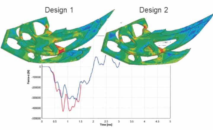
Figure 1: Notional Example of a Structure Evaluated via UBM Simulation to Consider Two Different Material Types (Source: ARL).
Later in the acquisition life cycle, when the system is mostly finalized but still requires evaluation and fine-tuning, testing may be conducted to more concretely determine the quality of a system. This sort of developmental testing is typically reduced in nature — the system may only consist of a floor, hull, etc. Additionally, tests may preclude anthropomorphic test devices (ATDs) (otherwise known as crash test dummies) due to the risk of loss or damage.
In cases where ATDs are omitted, an evaluator may still want to know what would have happened to an occupant. UBM, due to its modular nature, can produce injury estimates for a hypothetical occupant given measurements from accelerometers mounted in appropriate structural locations, such as the floor or wall. Essentially, UBM translates structural response data into injury predictions without an ATD expressly present in the test or simulation. This capability does not entirely obviate the benefit of using actual ATDs in testing, but it does augment otherwise limited test data under programmatic testing constraints.
As a system begins to undergo additional testing, stakeholders (program managers, evaluators, engineers, testers, etc.) determine the range of test parameters, including threat size and location, and the number of tests feasible within allotted resources. UBM can be employed to considerably optimize those limited resources by simulating tests throughout the experimental space, then identifying the most advantageous conditions or suspected vulnerable areas to look out for during testing.
Finally, once a system reaches formal LFT&E, UBM modeling can aid evaluators, engineers, and designers by exploring system response against untested conditions. Because live-fire testing is resource-intensive, modeling support is often required for answering questions unaddressed by the test matrix. Examples are often along the lines of the following:
- “What would have happened if the blast was of a greater magnitude?”
- “At what point does the hull rupture?”
- “What is the actual cutoff for our protection level?”
- “What if our underbody kit had been a little thicker?”
Once UBM receives accreditation to provide modeling and simulation (M&S) support for a given system, simulations can be performed to expand the experimental space considerably.
In summary, UBM can provide impact to programs across a system’s acquisition life cycle by leveraging a flexible, hybrid approach to UBB M&S.
UBM can provide impact to programs across a system’s acquisition life cycle by leveraging a flexible, hybrid approach to UBB M&S.
UBM PROCESS AND TOOLSET OVERVIEWS
Figure 2 illustrates the UBM process. The boxes and images surrounding the flow chart in the center illustrate the suite of tools available to accomplish the functions to which they are linked. The modeling process begins with blast loading (the red-shaded boxes) and vehicle response (the green-shaded boxes) as a coupled event, meaning that they occur simultaneously and each phenomenon influences the other. The vehicle response produces outputs such as local floor and seat-mount motion that are fed to independent subsystem models. These subsystem models, or submodels, generate simulated occupant responses (the orange-shaded boxes). The lower-leg methodology uses floor motion to predict response of an occupant’s lower legs (left branch), and the seat and occupant upper-body methodology uses the seat-mount motion to predict an occupant’s upper-body response (right branch). These specific modes of occupant response are then passed to the injury assessment tool, which predicts occupant injury/injuries due to the blast loading event.
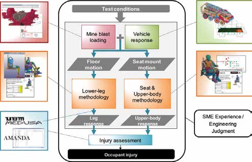
Figure 2: UBM Flowchart (Source: ARL).
Furthermore, the modular nature of the modeling process allows for significant input from subject-matter experts (SMEs). This expertise can be internal or external to the original set of modeling personnel. It should also be noted
that each process has several options associated with it in Figure 2, showing that there are numerous modeling options available to accomplish that process, depending on the fidelity required and resources available. Generally, there is a fast-running low-fidelity tool that is complemented with a slower, higher-fidelity option for situations where the additional complexity is necessary.
Regarding blast loading, there are the high-fidelity Arbitrary Lagrangian-Eulerian (ALE) algorithm and the fast-running Momentum Impulse Numerical Estimator (MINE) Suite of Codes (MSOC).
ALE is a loading technique that explicitly couples the soil, explosive, and vehicle elements within the finite element analysis (FEA) (in this case, an LS-DYNA execution). It tends to produce more accurate results but also requires a greater degree of modeler knowledge and significant computational resources.
MINE, on the other hand, is a numerical approximation of blast loading that is used to generate an impulse profile against an arbitrary target geometry. The finite element target vehicle is then run using the MINE-generated loading profile but without any of the Eulerian elements associated with ALE. The primary advantages of MINE are its government ownership, extremely fast run-time, and easy implementation as a stand-alone code. However, effectively using it in some scenarios can be difficult, as it requires familiarity with its numerical methodology to appropriately set up loading profiles.
Vehicle response, which is calculated concurrently with blast in the coupled methodology, also has high-fidelity (explicit finite element) and low-fidelity modeling options. The finite element approach (illustrated in Figure 3)
is typically desired; however, it can have longer lead times due to the level of effort that must be put into it and the requirement of detailed target geometries.
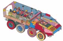
Figure 3: High-Fidelity Finite Element Model of an Example Vehicle (Source: ARL).
The low-fidelity option for vehicle response is called TRUCK, a mass-spring-damper representation of an otherwise rigid vehicle (Figure 4). Because of the simplification of the vehicle structure, this technique is exceedingly fast, but accurate output is limited to rigid-body motion.
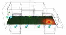
Figure 4: Screenshot From the TRUCK Model (Source: ARL).
For upper-body occupant-response methodologies, two options are again available: the high-fidelity Seat and Occupant Subsystem Model (SOSM) and the low-fidelity One-Dimensional Seat and Occupant Model (1D Model). SOSM is the occupant-only analogue to explicit vehicle modeling—every effort is made to accurately capture the seat geometry, materials, and behavior by carefully capturing as many details as possible. The 1D Model is somewhat akin to TRUCK, as it is a one-dimensional mass-spring-damper representation of the seat and the occupant’s upper body. As with TRUCK, the 1D Model is exceedingly fast, albeit somewhat limited in what it may accurately predict (e.g., lumbar spine forces are a known problem).
Additional occupant-response tools include the Lower-Leg Subsystem Model (LSM) and the Heel-Strike Subsystem Model (HSM), both of which model lower-leg response. Both are laboratory designed and optimized to focus exclusively on their respective injury metrics for minimum computation time without sacrificing accuracy. They are considered medium-fidelity because the occupant’s upper body has been removed to save computational time. Both are explicitly modeled portions of the ATD and seat models they would represent.
The Injury Predictor Tool (IPT) is the final response option. This is a meta-model (effectively a look-up table) of results from simulations of parameterized SOSM runs. This tool is unique in that it can produce both lower-leg and upper-body responses.
For injury assessment, AMANDA, or Analysis of Manikin Data, is the Army’s validated method for evaluating injury from time-series data. This tool is used exclusively as a library for a more comprehensive tool, the Modular Engine for Development of Underbody Blast System Analyses (MEDUSA).
Internally, MEDUSA is used to handle data flow from process to process. MEDUSA’s functions are illustrated by the blue arrows in the flowchart in the upper-left corner of the previous figures, and described in Figure 2. Besides handling data flow, MEDUSA is also capable of a wide variety of utility tasks, such as generating meshes, error-checking model decks, post-processing data, and generating documentation.
CURRENT STATUS AND NEXT STEPS
Currently, UBM is undergoing VV&A in accordance with relevant Army standards to support the live-fire testing of ground vehicle systems. A more detailed discussion of VV&A efforts is found in the following section.
Note that these tools and capabilities are not set in stone; UBM is an evolving capability that continues to adapt to suit the needs of the live-fire community. The development effort is proactively moving toward enhancing UBM’s capabilities by adding various injury metrics, investigating human body modeling to replace ATD submodels, modeling shock and fragmentation effects, and other features.
VERIFICATION AND VALIDATION (V&V) OF THE UBM TOOLS
The V&V of UBM is focused on tools to be used in support of ground vehicle LFT&E programs. Tools that offer the highest fidelity were selected for this application: ALE’s loading methodology paired with an explicit finite element target model; LSM and SOSM for lower-leg and upper-body response, respectively; and MEDUSA/AMANDA for injury assessments. Injury assessments will be based on tibia compressive force and dynamic response index (DRI), a metric related to spinal injury derived from pelvis acceleration.
The first step in V&V is verification—demonstrating that the tools do what they are supposed to be doing. The operative approach to UBM verification was to verify each of the tools individually and then to verify the methodology as a whole. This strategy, sometimes called verification by incorporation, is particularly well-suited to a modular process such as this one.
Verification entails checking that modeling parameters match those from the test (e.g., verifying the correct charge mass and dimensions, vehicle geometry and mass, soil properties, and ATD boundary conditions). It also consists of verifying that appropriate mesh size and element densities are used in the model and that the simulation is set up according to published standard operating procedures.
Verifying such a complex methodology can present many challenges. For example:
- Schedule and other resource limitations mean that every aspect of UBM-constituent models cannot be verified. However, numerous variables were selected for output sensitivity as a way to focus available resources.
- LS-DYNA is “black box” software, meaning that the source code is inaccessible. Therefore, specific equations and processes cannot be verified for correct implementation. Instead, a number of simple test cases with varying parameters were tested for the reasonableness of their results and the correspondence between parameter variation and output trends.
- Proprietary material properties pose a challenge because they cannot be interrogated to confirm their constituent properties. Many vendors incorporate such materials in the models that they create
and provide. To help mitigate this risk, test data and development documentation are requested to enhance confidence in the material models as implemented. - Continuing improvement and refinement of tools and techniques, as well as working to develop new ones, create a “moving target” for the verification task. To perform the on-record VV&A, the tools and methodologies to be used for a specific program are frozen in their state for VV&A while development continues for other applications.
While verification aims to determine that the tools are working as they are intended to work, validation goes further to then determine whether they are doing so accurately from the perspective of the intended use. UBM applications often involve some tie-in to real-world events. Therefore, validation leans heavily on comparing test results to simulation predictions.
The overarching validation philosophy for UBM is to compare simulations with UBB tests of increasing complexity and/or realism. For example, simulated targets include a rigid flat plate, a small-scale V-hull, a generic vehicle hull, a modified ground vehicle, and full-up system-level test assets. This validation methodology helps to reveal changes in accuracy as a function of test complexity and thus increases knowledge and confidence in the application of UBM tools.
A three-pronged approach for validation of UBM was undertaken. First, the ALE loading on a structure was validated. Second, the occupant subsystem models were validated. Third, the integrated, end-to-end UBM process was validated on a complex event.
The overarching validation philosophy for UBM is to compare simulations with UBB tests of increasing complexity and/or realism.
ALE loading and finite element structural response are validated together because loading by itself cannot be measured directly. Therefore, the most straightforward way of measuring blast loading is applying it to a structure with predictable response patterns and measuring the loading’s effect on the structure. To this end, simulation results are compared to testing via metrics of the structure’s response that can be measured directly. Tests against simple, small-scale targets allow for high-quality local response data. For instance, the stereo digital-image correlation (SDIC) measurement technique was used to gather displacement data during the small-scale V-hull test series (Figure 5).
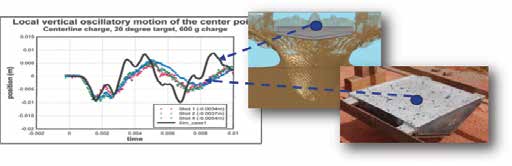
Figure 5: Notional Example Comparing SDIC Test Measurements to Simulation Results for UBM Validation (Source: ARL).
As the targets become more complex and realistic, up to a full-size vehicle, validation of the loading and structural response becomes difficult. Full-scale tests are exponentially more expensive, and thus the quantity of available data can be extremely limited.
One common comparison metric is the jump height of the vehicle as measured from high-speed video. Another metric might be plastic hull deformation. Three-dimensional laser scans of the vehicle hull after the underbody test can be compared to contour plots of the deformed hull taken from the simulation. Structure or component damage is also a useful metric. Damage observations from test cases can be used to interrogate the simulation to see if regions of high strain or failure at or near that component were predicted.
The second prong in the three-pronged validation approach is validation of the occupant subsystem models. These models are independent of the vehicle structural model so they can be evaluated separately. They produce a prediction of occupant response given a prescribed excitation (loading) dictated by the local structural response.
As with the overall vehicle model, these models are validated by comparing simulation results to tests of increasing complexity. In this case, the simplest tests include controlled, laboratory tests. A second tier of complexity uses an accelerative loading fixture, where the structure is simplified and its response is tightly measured, but the loading is produced from an actual UBB to increase realism. The most realistic tests are from full-scale vehicle testing in which occupants are seated in a vehicle that is subject to an actual UBB event.
The third prong of the validation approach is to compare simulation results from the entire integrated, end-to-end UBM methodology to live-fire tests. This comparison involves repeating the type of work described in the first two prongs of the validation approach but in a single exercise. The key difference is that errors from the loading and vehicle response simulations might exacerbate, mitigate, or have no effect on errors from the occupant response and injury phases. Metrics for validation might include the entire set previously mentioned: jump height, hull deformation, occupant response time histories, and injury assessments. A full “walk-through” example case, notionally done to support a live-fire pre-shot prediction, is discussed in detail in the following section.
SIMULATING A TEST (UBM WALKTHROUGH)
The final part of this article discusses a demonstration of how UBM is typically applied to live-fire support—specifically, how it will be applied to advance its case for accreditation. This LFT&E support process is a necessary extension of the V&V process. As discussed previously, once accreditation is achieved, UBM can be applied in additional ways, including supplementing physical testing with simulations of additional conditions.
Before M&S can be conducted, the models need to be prepared. A finite element model of the vehicle must be built, or received and edited, along with an ALE mesh. The model and mesh are built according to published standard operating procedures.
Additionally, the occupant submodels must be built. SOSM represents a specific seat, so a finite element model of an ATD in the system-specific seat must be constructed. A library of standards-compliant SOSMs is being populated to reduce production time in the future. It should also be noted that laboratory-scale testing is performed on the seat to be used to validate the SOSM characterization parameters.
LSM features a representation of floor blast mats that must be characterized from laboratory testing, along with the SOSM seat. As with SOSM, a library of blast mat characteristics is being collected so that the appropriate mat properties can be simply pulled from the library if they are already available.
As the simulation is being constructed, a checklist is followed to verify that the correct parameters are being used; for example, test photographs of the vehicle can be overlaid on the vehicle model to verify corresponding geometries (Figure 6).
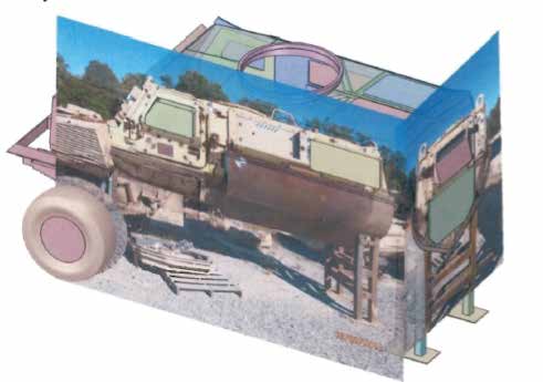
Figure 6: Notional Example of Comparing a Simulation to Test Photographs to Verify Vehicle Model’s Geometry (Source: ARL).
The measured test results are compared to the simulation predictions across numerous metrics (many of which have been mentioned previously), including gross vehicle motion, local structural response, injury assessment, and occupant response.
High-speed video of the vehicle’s gross (approximately rigid-body) motion during testing is compared to similar displacements calculated in the simulation. A comparison of the local plastic structural response aids in showing that the load is correctly applied spatially to a well-behaved vehicle model. Additionally, the simulation is evaluated by comparing predicted component damage and other dynamic events (e.g., a battery box striking a wall or a floor rising up and impacting a seat).
Faithful comparisons of the vehicle’s gross motion, hull deformation, component damage, and dynamic events give good confidence that the loading and vehicle models are accurate. Assuming sufficient success, the next step is to compare occupant injuries.
A top-level comparison of the assessed injuries is the first one performed. The injury predictions for each metric per occupant are compared to those observed in the test results. These comparisons form a tally of agreement/disagreement between modeling and testing. Currently, UBM focuses specifically on lower tibia and DRI injuries, so injury assessments for these metrics for each occupant are the relevant comparisons.
Beyond the top-level comparison of injury predictions is a comparison of response time histories of the occupants (Figure 7). This consists of a comparison of tibia force time histories (for LSM) and DRI time histories (for SOSM). The comparisons provide information about the difference between relative indices (the percentage of an injury metric as compared to its injury threshold) as well as the quality of the agreement in shape and timing of the responses.
The accreditation decision will proceed based on the results of these comparison exercises. Generally “good” comparisons yield accreditation, and then UBM will be used to generate additional predictions as required to enhance the vehicle evaluation. There may be cases in which the model does not match the test well, but it is possible to still receive limited accreditation for, say, predicting qualitative trends or for certain subsets of the evaluation space.
If the model does not generally match the test well, then investigation will yield possible explanations, updates for the model or modeling techniques (where applicable), and a rerun of the test scenarios. Potential sources of error include the possibility that the model was not set up in the same way as the test was conducted, the vehicle model differed from the actual tested vehicle, and/or of the occupant models did not represent how they were actually tested. Nevertheless, the improvement cycle exists so that the model can be improved for future accreditation. Ultimately, the goal remains to show good model-to-test comparisons across all the criteria, thus building the cumulative case that the model is predicting the right results (injuries) for the right reasons.
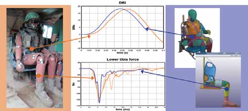
Figure 7: Notional Example of a Comparison Between Occupant Injury Test Measurements and UBM Results (Source: ARL).
SUMMARY
UBM, in its current state, can be used for (1) live-fire test planning and shot prioritization, (2) design trade-offs and recommendations, (3) AoAs, and (4) live-fire pre-shot predictions. The specific use of UBM for official live-fire pre-shot predictions will ultimately inform a model accreditation decision. Accreditation is based on successful verification of the methodology and model inputs, as well as validation of model results. Validation is achieved by comparison of model predictions to measured test results using the following metrics: gross vehicle motion, local structural response, injury assessment, and occupant response. Successful accreditation allows UBM results to be used for expansion of test data to a broader set of threats, systems, and contexts that would otherwise be limited due to resource constraints. UBM will result in enhanced ground vehicle evaluations and, ultimately, improved vehicle and occupant survivability against buried blast threats.