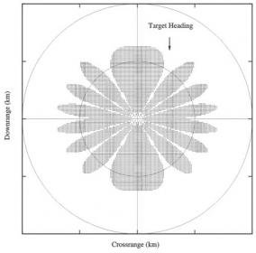
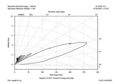
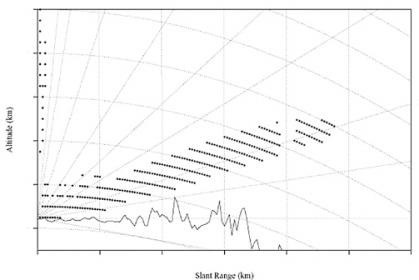
The Advanced Low Altitude Radar Model, or ALARM, is a generic digital computer simulation designed to evaluate the performance of a ground-based radar system attempting to detect low-altitude aircraft. The purpose of ALARM is to provide a radar analyst with a software simulation tool to evaluate the detection performance of a ground-based radar system against the target of interest in a realistic environment. The model can simulate pulsed/Moving Target Indicator (MTI), and Pulse Doppler (PD)-type radar systems and has a limited capability to model Continuous Wave (CW) radar. Radar detection calculations are based on the Signal-to-Noise (S/N) radar range equations commonly used in radar analysis. ALARM has four simulation modes: Flight Path Analysis (FPA) mode, Horizontal Detection Contour (HDC) mode, Vertical Coverage Envelope (VCE) mode, and Vertical Detection Contour (VDC) mode.
The primary application of ALARM is the evaluation of target detection range as a function of the environment. The model now includes the environmental effects of atmosphere, terrain masking, clutter, multipath, and electromagnetic propagation through the use of Joint Aircraft Survivability Program Common Modeling Component Set (JASP CMCS). Land clutter reflectivity probability distributions published by the Massachusetts Institute of Technology (MIT) Lincoln Laboratory and sea clutter reflectivity probability distribution from the Center for Naval Analysis (CNA) are also used in ALARM. Pattern propagation effects such as radar antenna pattern, spherical earth and knife edge diffraction, and multipath are included by use of the MIT Lincoln Labs Spherical Earth/Knife Edge (SEKE) Diffraction source code. Terrain masking is determined based on National Geospatial Intelligence Agency (NGA) Digital Terrain Elevation Data (DTED), which is put into the model for a specific radar site area. Additionally, ALARM supports limited modeling of onboard noise (self-screening) jammers, onboard deception (coherent) jammers, and standoff noise jammers.


